Skin Conductance Response (SCR) in Orienting and Habituation.
In this simple example of use of the PSYLAB PCC script to organize stimulation, tone stimuli are presented with pseudo random Inter Stimulus Intervals of between 20 and 30 seconds. The TG/WN stimulator is attached to one side of a SAM unit, and typically an SC coupler attached to the other side. Any number of measurement amplifiers may be used in this or any other experiment, SAM1 software will automatically measure from whichever devices are attached, but for the classic OR example, SC Specific Response (SR) to each stimulus is the measure most commonly observed. When three stimuli in turn fail to produce an SR the subject is said to have habituated.
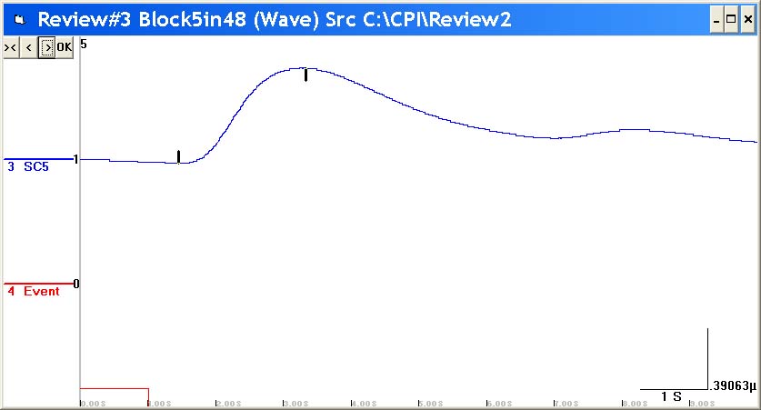
Typical SC response to a stimulus. A Specific Response (SR) is normally said to be valid if its onset point, marked by the vertical dash above the base of the response curve, occurs in a time window 1 to 4 seconds after stimulus onset.
Equipment list.
- 1 SAM Stand Alone Monitor unit
- 1 SC5 Skin Conductance Amplifier
- 1 TG/WN Sound generator
- 1 PHON Headphones
- 1 EL1 Set of SC electrodes TDE22
- 1 PSU Power supply unit
- 1 PSY PSYLAB software
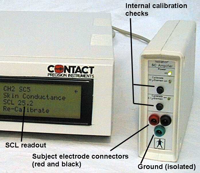
SC equipment used in the Orienting response experiment.
Setting-up the hardware.
- Plug the SC5 Amplifier on to the left side of the SAM unit, using the 15 way male/male high density cannon cable provided.
- Plug the TG/WN on the right side via similar cable.
- Plug the Power Unit into the power socket at back of SAM unit.
- Join the SAM unit to the computer using the USB cable provided.
- Install PSYLAB software on the computer before switching on the SAM unit.
Setting the SAM controls.
Settings for the auditory stimulator are automatically controlled by PSYLAB software. Values displayed for the stimulator in the right side of the SAM LCD panel can be ignored.
Settings for the SC5 Amplifier are also completely automatic, the device sends full 24 bit resolution SC data to the host computer at the selected sample rate. This high resolution makes gain control etc. unecessary - data may be re-scaled in software if required
Positioning the subject.
SC measurement is extremely robust and is most unlikely to suffer interference wherever the subject is positioned. The SC Amplifier and the TG/WN stimulator may be placed near to the subject using the extension cables provided.
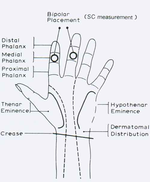
Positioning the electrodes.
Two 8mm diameter measuring electrodes (part no EL1 TDE22) may be positioned on the hand. Suitable adhesive collars are supplied with these re-usable electrodes. Peel off the backing from one side of the collar and stick it onto the electrode so that it does not obscure the active area of the electrode. Then fill the electrode with TD 246 jell, so that the jell is flush with the electrode/collar surface. Wipe away excess jell, then peel off the other surface of the collar, taking care not to get jell on the sticky surface. Apply the electrode to the skin, pressing firmly so that it sticks in position. It must be well enough attached to remain in position for the duration of the procedure. Standardized procedures should be used regarding subject preparation, e.g. either do not ask the subject to wash hands, or always do so, as washing may affect the SC measure. It does not matter which of the two electrodes is plugged into which of the red and black sockets of the amplifier. The green socket is unusued.
Software configuration.
The first time the SAM1 program is started, make the following adjustments:
Set the SAM Properties window to:
- Acuisition sample rate 1000 (samples per second)*
- Idling sample rate 300 (samples per second)
- Graph speed 20%
- Buffer 1024 bytes
* Note that any acquisition sample rate 100 or above may be chosen. For SC measurement, only a low sample rate is required, but if other measures are also included hegher acquisition sample rate may be necessary;.
In the PCC menu, check the following options:
- Prompt to open PCC file
- Run PCC program when acquiring
- Use metacommands
After making these changes, Use File, Save settings now., to retain these settings.
PCC program used to run the experiment.
The following code may be copied to the PCC editor window and saved to disk.
Ĺ Orienting response PCC program
$table 25,30,20,23,27,20,30,25,22,28 Ĺ set ISI intervals
t1 = 5
MAIN
if time = t1 then gosub STIM
goto MAIN
STIM
stimNo = stimNo + 1
t1 = t1 + table(stimNo)
if StimNo = 11 then store ' end experiment
t1 = t1 + table(stimNo) ' get inter trial interval
setTone 3,200,100,100,2,1
Ĺ CS tone stimulus both ears, vol 200, event code 100,
Ĺ frequency 100 (1kHz), attack decay 2 (50mS), duration 1 sec
latency = 0
delay until latency > 1
startStim
return
The example program produces a series of 10 tone trials to observe habituation. The script file may be enlarged and developed to accommodate virtually any stimulation sequence that may be needed. The script directly controls the PSYLAB Tone Generator
The entire experiment requires just a few lines of the BASIC like PSYLAB Command Code (PCC). Such code may seem complicated but it has enormous advantages over systems which use limited menu selections for choosing stimulus delivery. Normally, CPI will create the first programs a user requires for their particular tasks, there is also on-line help and e-mail support, whereby programs may be easily exchanged.
With the example shown, program execution begins from the top line when data acquisition starts and the measured wave-forms are seen on the screen. The top line of all PCC programs must be a remark, beginning with the single inverted comma character, and is usually a description of the program. Each line is interpreted in succession until a goto, gosub, return or end statement is encountered. In this case program execution loops in the MAIN section, waiting for the conditional Ĺifů thenůĺ statement to become true. This statement uses the function Ĺtimeĺ, real time into the experiment expressed in seconds, as one of the compared expressions, thus at the time defined by variable t1 execution will jump to the subroutine STIM, which control stimulus presentation. Variable t1 is increased by pseudo randomised values defined in the $table statement at the top of the program. It is used to set the time of the next stimulus. The Ĺreturnĺ statement causes a jump back to the line after the conditional jump, i.e. back into the MAIN loop. Data acquisition ends after the 10th stimulus.
Back to PSYLAB Hardware
Back to PSYLAB Software
Back to Home page