TMP5 Digital temperature coupler
|
TMP5 Digital temperature coupler |
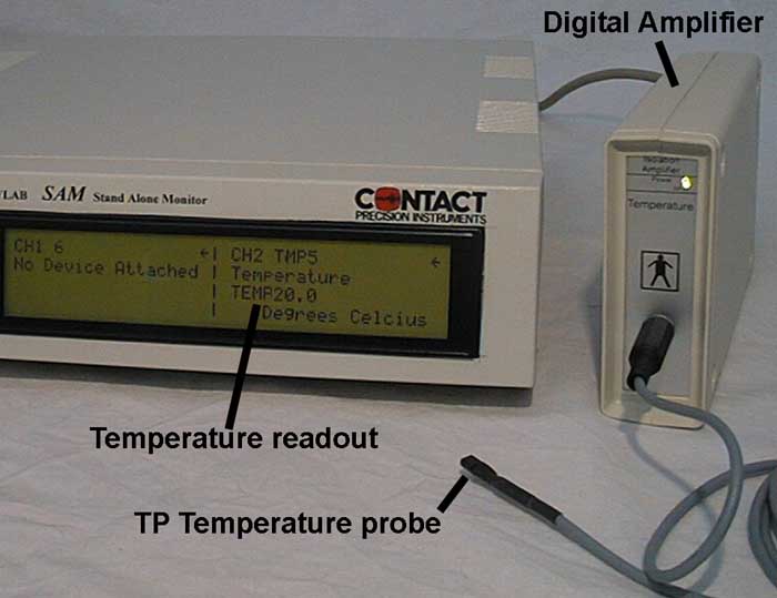 |
The main unit contains a micro-controller to co-ordinate communication with the pre-amplifier and send data to the host computer. It also provides two D-A converters allowing analogue output of temperature level (baseline) and fluctuation signal (DC coupled), each to 18 bit resolution. Used in this way, it may be connected to any A-D data acquisition system. An active linearized temperature probe (TP) converts temperature into voltage levels. This is diectly converted to digital, using a 24 bit A-D converter. Serial data are then transferred across the medical grade optical isolation barrier to the host unit. The temperature probe may be attached to the skin (e.g. finger). It should be taped in position using micropore or similar tape, with cotton wool to protect it from the air. If it is intended to measure body temperature, the probe should be suitably adapted for internal use. The probe is suitable for positioning externally on the body; modification is needed to protect it from fluids if it is used internally. When used externally, cotton wool will prevent heat conduction away from the probe, otherwise drafts in the room will cause noticeable temperature fluctuations. |
 |
||
 |
||
Illustration: Temperature changes in the left and right hands during a conditioning experiment of 800 seconds duration. The coordinates panel (right) shows absolute temperature readout at the point where the vertical black line has been scored on the temperature traces. |
|
|
|||||||||||||
An active linearized temperature probe (TP) converts temperature into voltage @ 10mV per degree centigrade. This is directly digitized, using a 24 bit A-D converter. Serial data are then transferred across the medical grade optical isolation barrier to the SAM unit. The temperature probe may be attached to the skin (e.g. finger). It should be taped in position using micropore or similar tape, with cotton wool to protect it from the air. If it is intended to measure body temperature, the probe should be suitably adapted for internal use. The probe is suitable for positioning externally on the body; modification is needed to protect it from fluids if it is used internally. When used externally, cotton wool will prevent heat conduction away from the probe, otherwise drafts in the room will cause noticeable temperature fluctuations. Specification: Absolute accuracy: limited only by measuring probe (~ 0.4 degrees) Resolution: 5.96e-6 degrees Celsius (theoretically) Safety isolation: 6000V Frequency response:10Hz Internal sampling frequency:40Hz Analogue outputs:18bit, +/- 5V, 9 way cannon socket. 2 x 18 bit
Functional details. The pre-amplifier is contained in an isolated plastic box, with electrical power conveyed to the circuit by a high quality medical isolating DC - DC converter. This ensures low noise with complete safety and individual isolation of electrode connections to prevent interaction with other amplifiers. Serial temperature data is fed across the isolation barrier in the pre-amplifier and passed via the connecting cable to the main unit. Here a micro-controller organizes data collection and passes information to output devices including direct digital connection to the PSYLAB host computer and the analogue outputs. Temperature level is shown on the LCD display, which is also used to show menu selection options. A 10 Hz filter is applied to the signal from the temperature probe to prevent aliasing. Pre-amplifier sample rate is 40Hz. When TMP5 is first turned on, it automatically calibrates itself, by switching first to precision voltage levels representing 0 degrees, then to 100 degrees. Having established these two points, it calculates the 'A' and 'B' constants required to correctly scale the entire range in-between in an Ax + B type floating point equation. Two analogue output modes are provided, determined by the settings in the parameters screen. To get to this screen, click on the arrow in the top right corner of the LCD display section. Mode 0. In this mode, temperature is expressed on both D-A converters so that +5V is 0 degrees and -5V is 100 degrees. Mode 1. In this second mode, the most significant section of the temperature data (temperature 'level') is sent to one D-A converter, and the lower significance section (which shows up very small temperature changes) is sent to the other. When this 'response' signal reaches +5V or -5V, the temperature 'level' changes by one step. The response signal is manipulated so that when it reaches +5V or -5V, the 'level' signal changes but the 'response' signal jumps to 0 Volts rather than all the way to the other extreme. This way, the 'response' signal tends to remain in a useful range to be directly viewed using conventional graphing software, as well as containing the high-resolution part of the data for logging purposes. The dividing point between the 'level' and 'response' part of the data is chosen such that the full scale 'response' signal represents 1.5625 degrees C. Analogue output connection. Analogue output is obtained on the analogue socket for the particular side of SAM being used by the amplifier. In mode 1 pin 5 is response, and pin 4 is level. In mode 0 both pin 5 and pin 4 carry the full (18 bit DAC) signal. The analogue output section has a separate ground from the main chassis of the SAM. The shell of the output socket carries this ground, which should be connected to the 3rd party data acquisition system ground. If the acquisition system has differential input, use the negative input for the analogue ground and connect the SAM chassis ground to earth. |
||